PSI Ring Turn separation
The PSI Ring parameters are not well-known. The goal of this study is to find good simulation parameters that match the measurements. As objectives we use the radial turn locations. As optimisation parameters we use the injection angle, radius, energy and radial momentum.
The OPAL probe code has been extended to find the radial turn locations in the same way as in the measurement, see figure below.
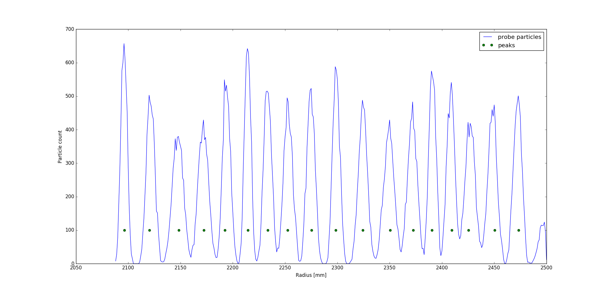
RRI2 probe simulation histogram (for 5000 particles) with found peak locations.
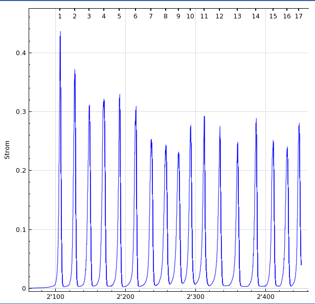
RRI2 probe measurement with peak locations.
Initial Test
First trial of optimizing three objectives:
- difference between simulation and measurement of peak 1
- difference between simulation and measurement of peak 2
- difference between simulation and measurement of peak 3 up to 5
Settings
- 1000 generations,
- 32 cores
- 500 particles
- no space charge
- 7 turns
IF ( _optpilot_ ) {
    // ---- OPTIMIZER SECTION -------
    //dphiinit: DVAR, VARIABLE="phiinit", LOWERBOUND="106", UPPERBOUND="114";
    //drinit: DVAR, VARIABLE="rinit", LOWERBOUND="2000", UPPERBOUND="2060";
    //dprinit: DVAR, VARIABLE="prinit", LOWERBOUND="-0.02", UPPERBOUND="-0.01";
    //dbenergy: DVAR, VARIABLE="benergy", LOWERBOUND="0.071", UPPERBOUND="0.072";
    //dvars: DVARS=(dphiinit,drinit,dprinit, dbenergy);

    //dpeak1:OBJECTIVE,EXPR="fabs(radialPeak("RRI2.peaks", 1) - radialPeak("RawData/RRI2-0038Y17.peaks", 1))";
    //dpeak2:OBJECTIVE,EXPR="fabs(radialPeak("RRI2.peaks", 2) - radialPeak("RawData/RRI2-0038Y17.peaks", 2))";
    //dpeak3_5:OBJECTIVE,EXPR="sumErrSqRadialPeak("RRI2.peaks", "RawData/RRI2-0038Y17.peaks", 3, 5)";

    //objs: OBJECTIVES=(dpeak1,dpeak2,dpeak3_5);
    //constrs: CONSTRAINTS = ();
    //opt: OPTIMIZE, OBJECTIVES = objs, DVARS = dvars, CONSTRAINTS = constrs;
 }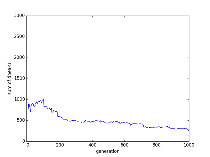
Sum of all differences (simulation - measurement) of peak 1 per generation.
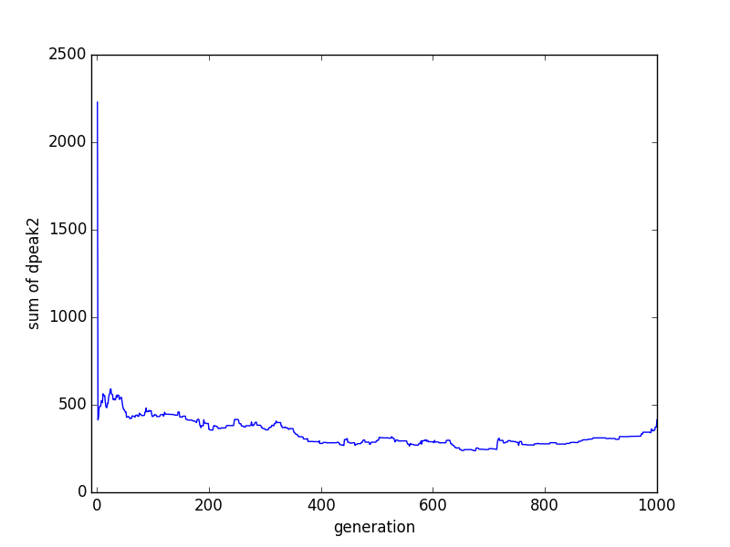
Sum of all differences (simulation - measurement) of peak 2 per generation.
Sum of all differences (simulation - measurement) of objective 3 per generation.
We see a nice decreasing curve for peak 1. Also the curve for peak 2 is mainly decreasing. However, the third objective is also increasing over the generations.
Results for one of the "best" (defined as the minimum of the sum of objectives) seeds:
%ID        %dpeak1        %dpeak2      %dpeak3_5 DVAR:       %benergy       %phiinit        %prinit         %rinit
25 42   4.500000e+00   3.000000e-01   5.174510e+00         7.120380e-02   1.098186e+02  -1.513638e-02   2.030688e+03
Probe measurement, simulation and measurement (scaled)
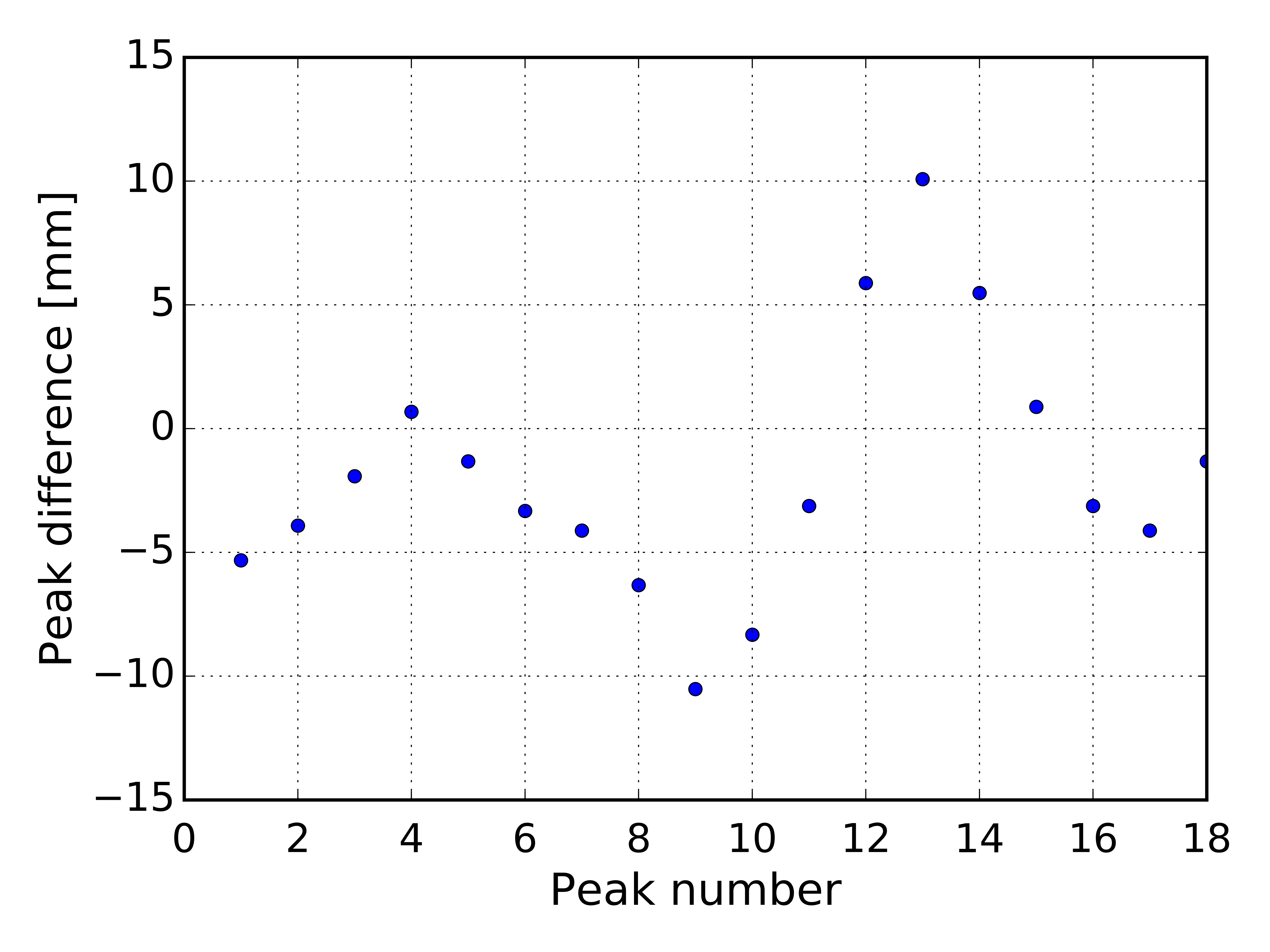
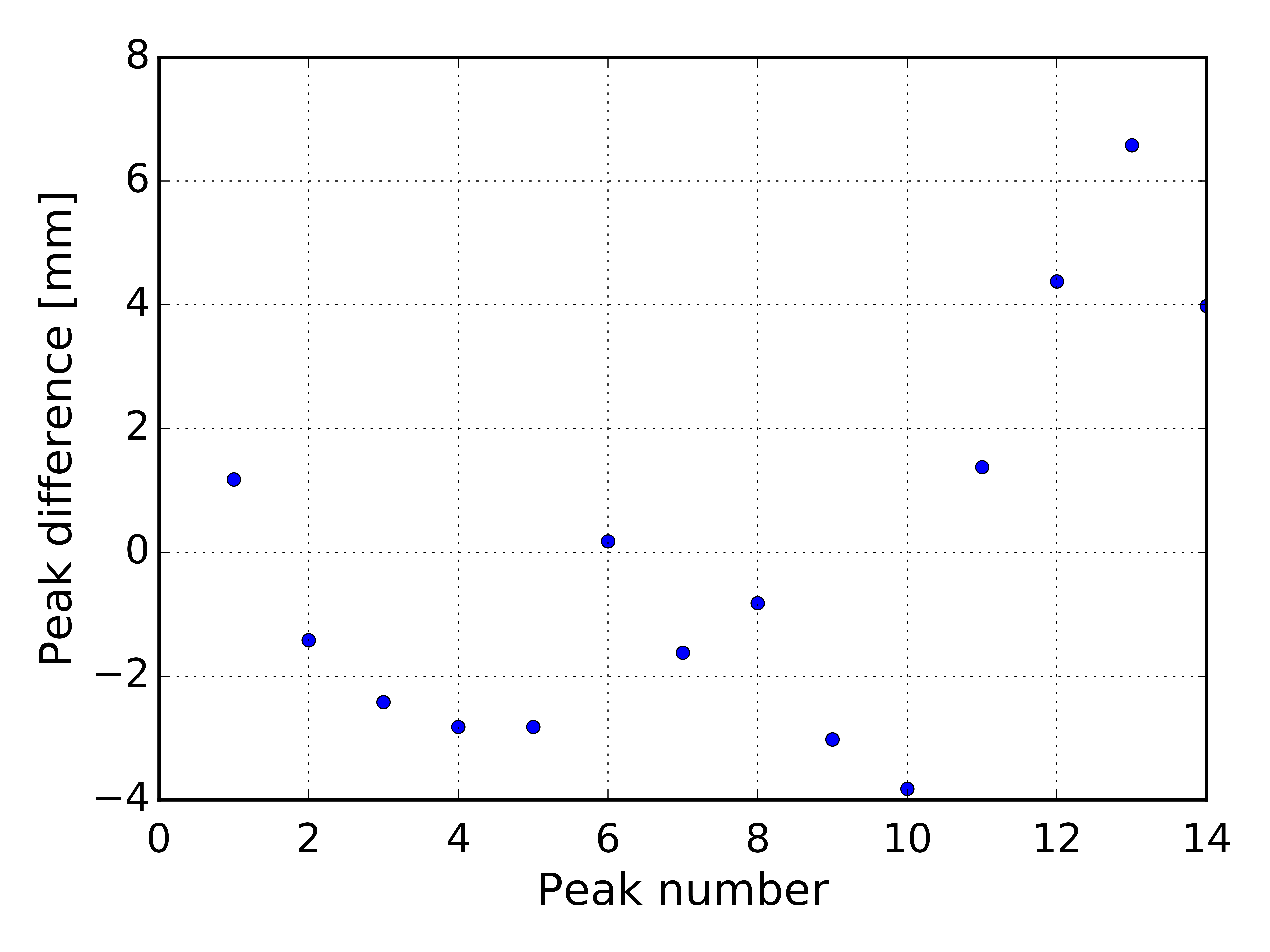
 Radial peak differences between simulation and measurement versus peak number.
Test 2
After the first test a number of changes were applied:
- The RRI2 measurement was changed to RRI2-0065Y08. This is a 300uA Strahlentwicklung measurement by Jianjun.
- The number of generations was increased to 10000.
- The cavity voltages were adapted to the measurement setting (looked up with
analyze):- vmaincav1 .7867 #[MV] RF Voltage on Main Cavity 1
- vmaincav2 .7734 #[MV] RF Voltage on Main Cavity 2
- vmaincav3 .7710 #[MV] RF Voltage on Main Cavity 3
- vmaincav4 .7876 #[MV] RF Voltage on Main Cavity 4
- B-Field of trim coils 1 (turns 1-4) and 2 (turns 1-7) were added to the design variables.
- Objectives: dpeak1, dpeak2, dpeak3_4, dpeak5_7
One of the best seeds was again selected:
%ID        %dpeak1        %dpeak2      %dpeak3_4      %dpeak5_7 DVAR:       %benergy       %phiinit        %prinit         %rinit        %tc01mb        %tc02mb
51 2.720000e+00 3.200000e-01 1.444022e+00 2.854766e+00 7.168652e-02 1.102582e+02 -1.438639e-02 2.040623e+03 -2.725981e-02 2.563253e-02 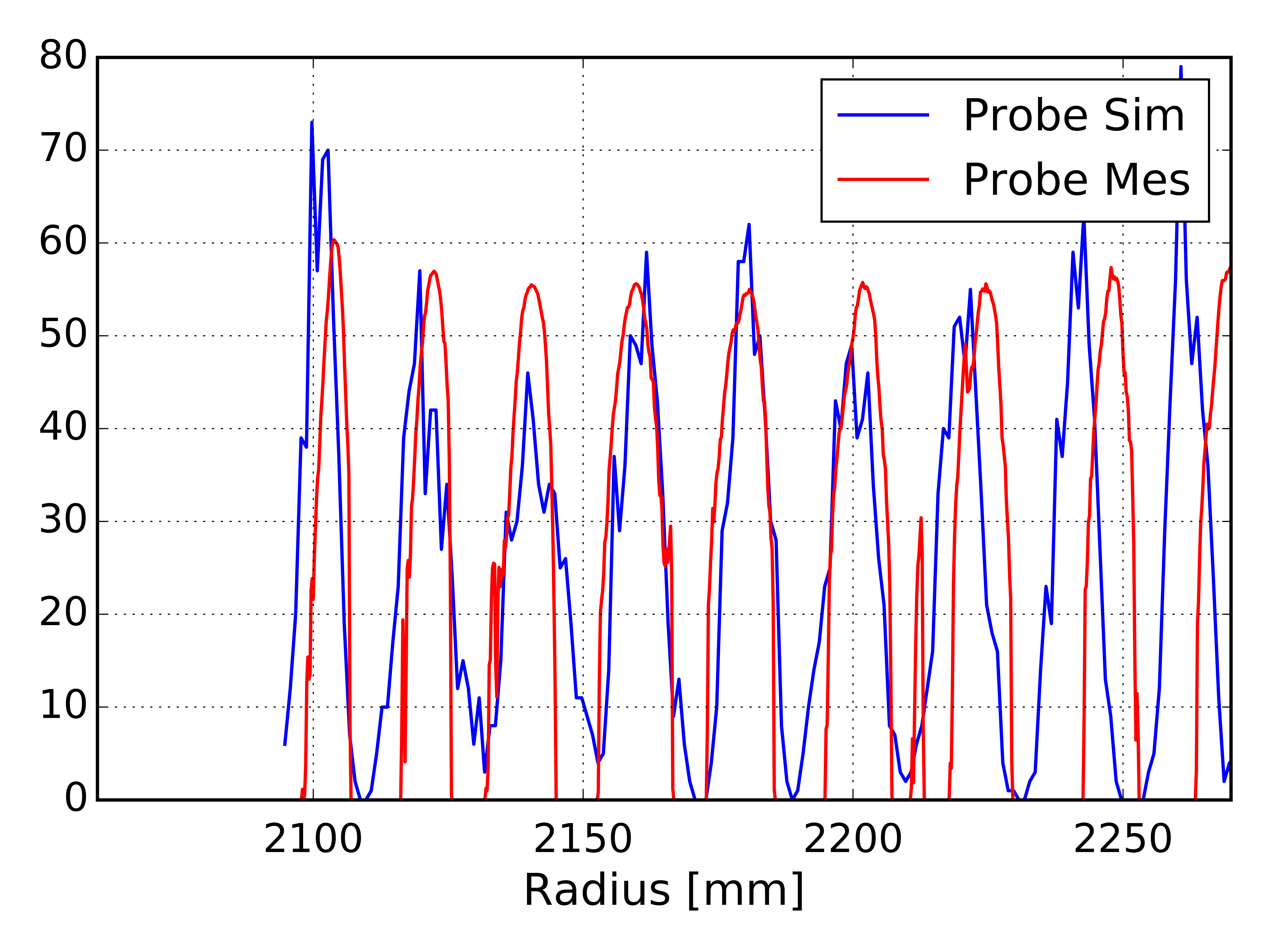
Probe measurement, simulation and measurement (scaled)
Radial peak differences between simulation and measurement versus peak number.
Test 3
- Add trim coil 3 (turns 1-13) to design variables
- Reduce range of design variables based on previous solutions
- Increase the initial population from 62 to 126. Due to the increased number of design variables the phase space is significantly increased.
- Reduce number of generations to 1000
- Objectives: dpeak1, dpeak2, dpeak3_4, dpeak5_7, dpeak8_13
Opt-pilot section:
   // ---- OPTIMIZER SECTION -------
   //dphiinit: DVAR, VARIABLE="phiinit", LOWERBOUND="108",    UPPERBOUND="111";
   //drinit:   DVAR, VARIABLE="rinit",   LOWERBOUND="2010",   UPPERBOUND="2060";
   //dprinit:  DVAR, VARIABLE="prinit",  LOWERBOUND="-0.02",  UPPERBOUND="-0.01";
   //dbenergy: DVAR, VARIABLE="benergy", LOWERBOUND="0.071",  UPPERBOUND="0.0724";
   //dtc01mb:  DVAR, VARIABLE="tc01mb",  LOWERBOUND="-0.046", UPPERBOUND="0.046";
   //dtc02mb:  DVAR, VARIABLE="tc02mb",  LOWERBOUND="-0.046", UPPERBOUND="0.046";
   //dtc03mb:  DVAR, VARIABLE="tc03mb",  LOWERBOUND="-0.046", UPPERBOUND="0.046";
   //dvars: DVARS=(dphiinit, drinit, dprinit, dbenergy, dtc01mb, dtc02mb, dtc03mb);

   //dpeak1:OBJECTIVE,EXPR="fabs(radialPeak("RRI2.peaks", 1) - radialPeak("RawData/RRI2-0065Y08.peaks", 1))";
   //dpeak2:OBJECTIVE,EXPR="fabs(radialPeak("RRI2.peaks", 2) - radialPeak("RawData/RRI2-0065Y08.peaks", 2))";
   //dpeak3_4:OBJECTIVE,EXPR="sumErrSqRadialPeak("RRI2.peaks",  "RawData/RRI2-0065Y08.peaks", 3, 4)";
   //dpeak5_7:OBJECTIVE,EXPR="sumErrSqRadialPeak("RRI2.peaks",  "RawData/RRI2-0065Y08.peaks", 5, 7)";
   //dpeak8_13:OBJECTIVE,EXPR="sumErrSqRadialPeak("RRI2.peaks", "RawData/RRI2-0065Y08.peaks", 8, 13)";

   //objs: OBJECTIVES=(dpeak1,dpeak2,dpeak3_4,dpeak5_7,dpeak8_13);
   //constrs: CONSTRAINTS = ();
   //opt: OPTIMIZE, OBJECTIVES = objs, DVARS = dvars, CONSTRAINTS = constrs;
%ID %dpeak1 %dpeak2 %dpeak3_4 %dpeak5_7 %dpeak8_13 DVAR: %benergy %phiinit %prinit %rinit %tc01mb %tc02mb %tc03mb
143 1.260000e+00 3.400000e-01 1.380507e+00 6.554727e-01 1.314424e+00 7.158339e-02 1.096083e+02 -1.760224e-02 2.043670e+03 -8.025304e-04 -2.966774e-03 -1.287497e-04 Video of the evolution of the pareto-front.
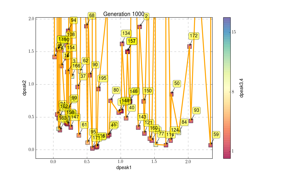
Zoomed Pareto-front. Some more generations might still be useful.
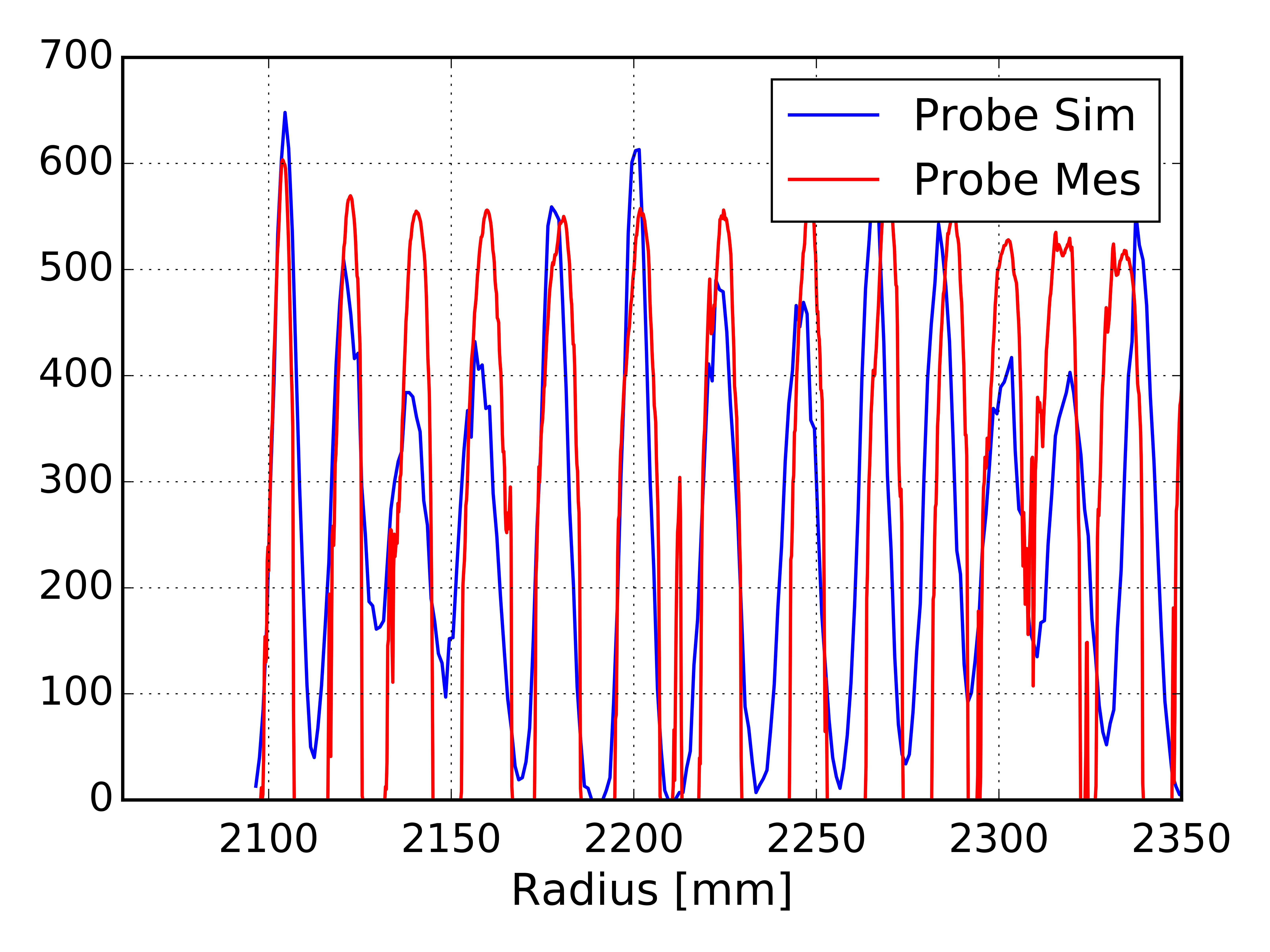
Probe measurement, simulation and measurement (scaled)
Radial peak differences between simulation and measurement versus peak number.
Test 4
The match is limited by the probe histogram bin size. This is expected to match better by:
- Reduce bin size of simulation probe.
- Increase number of particles